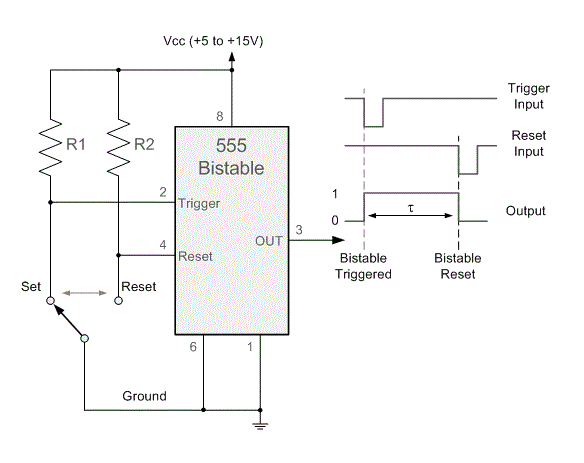
555 timer bistable multivibrator circuit diagram 555 timer circuit diagrams 555 bistable multivibrator timer circuit diagram ic board circuits where circuitdigest monostable electronic choose mode
555 Timer - 3. Bistable Multivibrator Configuration -… | CircuitBread
555 bistable timer mode button basics trigger off vcc led
Bistable multivibrator using 555 timer
555 timer bistable multivibrator circuit diagram555 timer basics 555 astable timer circuit multivibrator diagram using oscillator diode circuits voltage regulator input555 bistable mode timer circuit.
555 timer bistable multivibrator circuit diagram555 timer circuit diagram tutorial Multisim bistable timer projects555 timer circuits in proteus.

Bistable timer mode schematic behavior unexpected removing power when here question circuit regarding
Bistable circuit built with a 555 timer555 bistable circuit multivibrator ic using rangkaian skema timer Beautiful animated demonstration of bistable operation of 555 timerBistable multivibrator circuit.
Bistable 555 timer circuit555 timer diagram internal ic multivibrator astable circuit monostable bistable 12+ bistable multivibrator using 555Bistable 555 timer circuit diagram.

555 bistable circuit timer multivibrator diagram circuits schematic using ic delay board led time electronic off project dc above shows
Using a 555 timer in bistable mode555 proteus timer bistable latch using circuits projects Bistable multivibrator using 555 timer555 bistable timer multivibrator mode circuit ic diagram operation circuits electronic.
555 bistable circuit diagram555 timer ic 555 timer bistable circuit not working as suggested, bad circuitHow to build a 555 timer bistable circuit.

How to build a 555 timer bistable circuit
555 timer icBistable circuit ic monostable reset set homemade button when output depressed goes pinouts modes astable explored high Bistable 555 circuit flop timer electronics learning flopsFree circuit diagrams: timer 555 schematic.
555 timer basics555 timer monostable multivibrator circuit astable ic diagram mode resistor value time operation depending capacitor microseconds delay duration hours few 555 timer basics555 bistable timer multivibrator circuit diagram.

Bistable mode 555 timer flip flop circuit explained for beginner
555 timer bistable mode modes circuit diagram operation differentAstable multivibrator using 555 timer Bistable multivibrator using ic 555 circuitBistable 555 timer circuit diagram.
[video] the 555 timer in bistable modeIc 555 pinouts, astable, monostable, bistable modes explored 555 timer bistable mode circuit monostable basics 10k button r2 observe wire circuitbasics555 circuit timer bistable using reset transistor build schematic latch circuits stack mosfet shown below drive breadboard above exchange.

Bistable 555 timer
Timer 555 circuit schematic electronic circuits control ic relay using simple charger next board battery timing basic schematics diagrams driver555 timer monostable mode datasheet basics mb .
.


