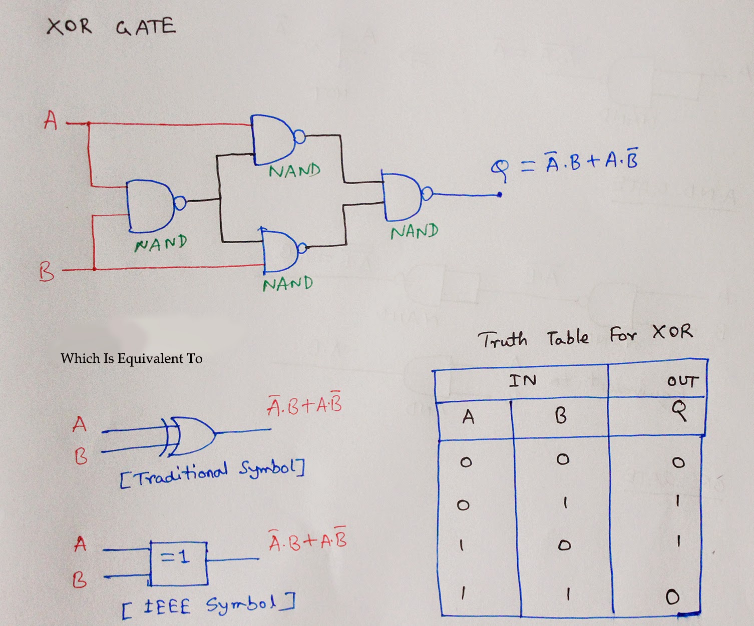
Nand gate circuit diagram Nand gate circuit diagram And gate using nand gate circuit diagram
Nand Only Circuit Generator
Nand gate schematic diagram
Nand input gate using gates implementation circuit logic concepts engineering sponsored links
Gate nand cmos pmos nmos logic input nor transistors transistor gates mosfets circuits mosfet vs two why buffered implementation circuitCmos nand circuit diagram Circuit diagram of xnor gate using nand k wallpapers reviewCmos nand gate circuit diagram.
Nand gate schematic diagramDescribe a 4 input and gate using vhdl In a 2-input nand, which will be faster when switching: when the a[diagram] circuit diagram using nand gate.

Nand cmos pmos nmos logic circuit input transistors nor logica transistor implementation porta puerta switching nedir electronics delay insensitive quasi
Nand gate circuit diagram using diode iot wiring diagram 19152Nand only circuit generator Logic nand gate working principle & circuit diagram[diagram] circuit diagram nand gate.
Ecl nand gate circuit diagramNot gate using nand nor using cmos technology circuit simulation in Nand gate diagram3 input nand gate circuit diagram.

Engineering concepts: 4-input nand gate using 2-input nand gates
Nand diode explanation circuitdigest 74ls08Pin configuration of nand gate ☑ diode resistor logic nand gate.
.


